THE SCAN FIELD CALIBRATOR
WHY TO CALIBRATE A SCAN FIELD?
A precisely calibrated process field is absolutely essential if the machine and laser are to work hand-in-hand and do their job perfectly.
The laser system’s optical and mechanical tolerances lead to deviation between the theoretical correction file and the real process field.
If high demands are placed on the laser beam’s positioning accuracy on the workpiece, these deviations need to be measured with extreme precision and the correction file needs to be updated with the precisely measured values.
Several problems arise when the process field is calibrated manually:
Significant time requirements
Limited correction accuracy
Countless opportunities to make mistakes
PRODUCT DESCRIPTION
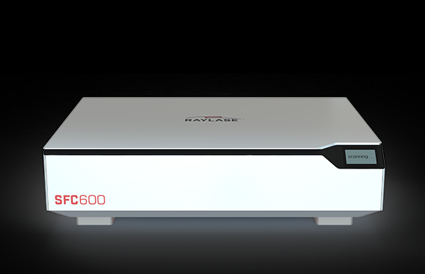
We have developed the new SCAN FIELD CALIBRATOR for the laser processing of large components that are particularly in demand in additive manufacturing and electromobility. It is making the transition from manual to automated calibration of laser process fields – even those of larger dimensions. At the same time, it offers unrivalled accuracy and enormously reduces the time and expense required previously: Agonisingly long measurements that take up staff resources become a thing of the past, at the same time quality, efficiency and cost-effectiveness in laser material processing increase.
ADVANTAGES AND BENEFITS
The SFC can calibrate fields measuring up to 600 x 600 mm² with a scan field correction accuracy in the
10-20 µm range. Even overlapping scan fields are automatically aligned to each other. The complete calibration process is performed with just a few quick clicks via a user interface (SFC GUI). The data is read out digitally and transferred to the SFC software. There is no media discontinuity, eliminating the need for the staff to have specific knowledge of the interface. All the measurement results are fully reliable, and the handling is very user-friendly due to Plug & Play. With regard to sustainability, you save costs since no additional measuring equipment is needed and you avoid waste, too.
TYPICAL APPLICATIONS
Additive manufacturing
Production of bipolar plates
Manufacturing of batteries
Production of large packaging
Structuring of photovoltaic cells
MANUAL VS. AUTOMATIC
MANUAL
Lots of steps do not always lead to the desired result! Manual scan field calibration is performed using coated plates that are sensitive to laser light to mark the calibration grid points. The measurement is performed manually, with the likes of a magnifying ruler. When calibrating the scan field in the machine, the calibration pattern must be measured line by line to the centre and to one another, and differences from the measured distances must be calculated. All the coordinates have to be entered manually into the calibration file’s editor. The measurement accuracy is ± 50 μm at best. A correction is made. Another ‘test shot’ is necessary to verify the accuracy. It’s a time-consuming process that runs a high risk of error, ties up key specialists for hours and days on end and requires an extremely high level of concentration – not to mention patience. So, what should you do?
AUTOMATIC
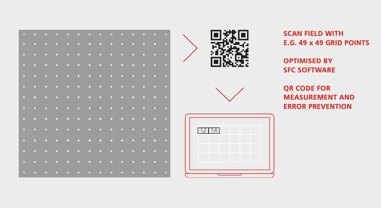
Calibrating a laser system’s process field with the SCAN FIELD CALIBRATOR is a totally different situation. With just a few clicks in the SFC software an optimised calibration pattern is lasered onto the calibration plate. The next click already triggers precise measurement of the grid points. With another click the measurement result is updated to the corresponding laser system. A QR code ensures that the correction is clearly assigned and that the possibility of application errors is excluded. Everything’s fully automatic! There’s no more need for a ‘test shot’ to verify accuracy. Calibration is done and dusted with unrivalled precision in five minutes flat. Even when dealing with larger process fields measuring up to 600 x 600 mm² and multi-field calibration of several process fields that are being processed in parallel, the time required and the machine downtime are both shortened by an incredible 96%.
CALIBRATION WITH THE SFC WITH 10 MACHINES IN PARALLEL
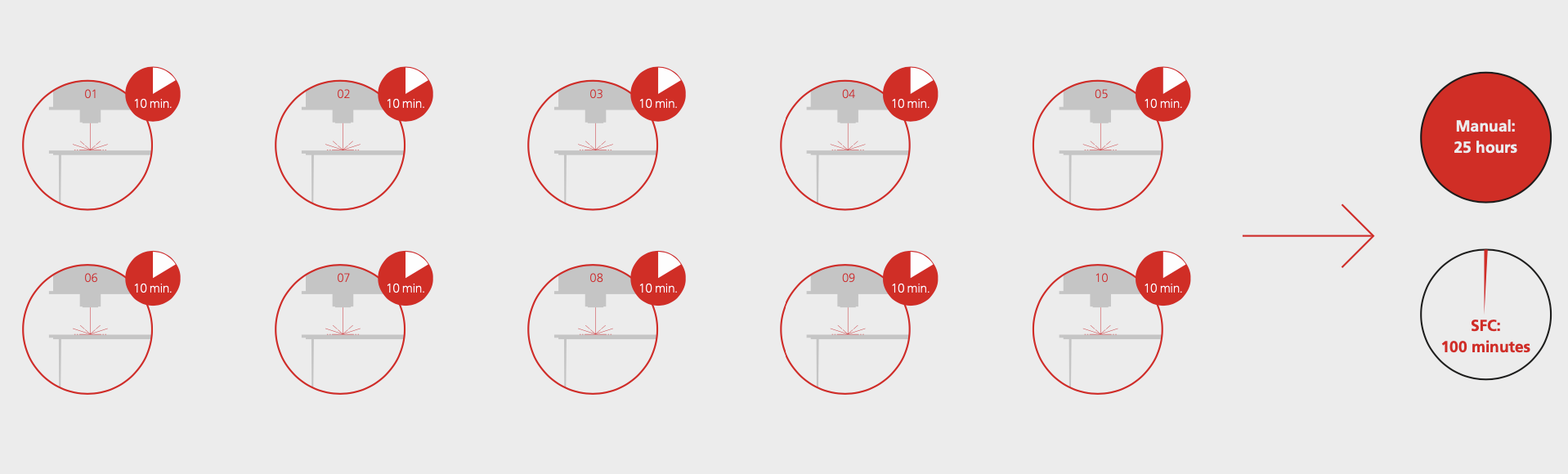
CONCLUSION: The SFC is easier on the stress level and time effi- cient. With 10 machines, the gain is over 23 hours.
Let’s assume that a car manufacturer wants all of its similar laser machines to produce as identical quality as possible for an identical laser job. To do so, it runs 10 machines in parallel to precisely laser cut its workpieces, and its process fields are 300 x 300 mm². It places an unused, identically sized calibration plate in each of its machines. Each machine is identified with its computer in a machine domain in the network.
The SFC-600 is in the same network domain. It is designed for process fields measuring up to 600 x 600 mm². Prompted by the SFC, the machine operators have all the laser machines mark the plates (i.e. laser them with the calibration job). Each calibration plate also receives a QR code. They then remove the ‘labelled’ calibration plates, insert them into the SFC one after the other and have them measured. The SFC stores the data specific to the laser system. After each scan, a decision is taken as to whether corrections should be made or whether the deviations are within tolerance.
If the user decides to make the correction, it is applied to the corresponding laser system. The total time required for all these steps on 10 machines is approx. 1 – 2 hours with the SFC from RAYLASE.
In contrast, if 10 laser systems were to be calibrated manually, the resolution would have to be significantly reduced to typically 5 x 5 and a maximum of 11 x 11 grid properties.
Two passes are typical in the case of manual measurement. At least two to three hours per machine should be allowed for this.
Conversely, this means two hours with the SFC compared to 20 – 30 hours of difficult manual work that calls for complete concentration.
UNRIVALLED IN TERMS OF PRECISION
THE SFC IS A QUANTUM LEAP
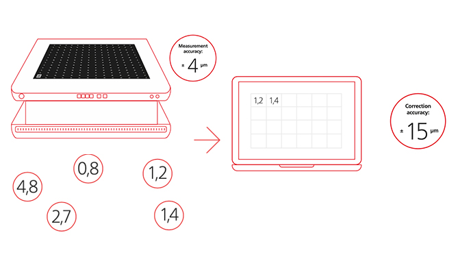
With the SFC, RAYLASE is revolutionising laser process field calibration. The accuracy of the measurement results is unbeatable. The SFC’s average measurement accuracy is ± 4 µm with a standard deviation of 2 µm. In other words, an average process field correction accuracy of ± 15 µm can be achieved. The measurement results can be viewed at any time if required, and access to the measurement history can be traced for each installation.
PERFORMANCE LIMITS OF MANUAL CALIBRATION
No manual calibration achieves this outstanding precision. Typically, 5 x 5 grid properties are measured manually, and manual measurement reaches its limits at 11 x 11 at most! With a manual measurement accuracy of ± 50 µm, the best that can be achieved is an average process field correction accuracy of ± 100 µm. So manual measurement isn’t suitable for calibration in additive manufacturing or electromobility. A minimum of 21 x 21 grid properties is recommended.
ABSOLUTE ACCURACY IN MULTI-FIELD CALIBRATION
Outstanding measurement quality can be achieved even in very complex applications with multi-fields. Here, the SFC offers a level of accuracy, an extraordinary homogeneity in multi-field calibration, that’s never been achieved before.
MULTI-FIELD CALIBRATION MADE EASY
SEVERAL LASER SYSTEMS IN ACTION
Let’s say we have a machine that can work either on four different workpieces with four lasers at the same time or on one workpiece with four beams. The ‘multi-field’ mode requires maximum precision and regular alignment of the scan fields. Only then can the workpieces that multi-laser manufacturing takes place on in parallel be a success.
The SFC performs the X-Y calibration of the four individual fields and their exact alignment to one another in a single step.
If you want to calibrate the sum of all four individual fields as a total process field, four calibration plates are lasered and measured with the SFC.
If only the intersection of the individual fields is to be calibrated as a process field, the number of calibration plates and measuring procedures is reduced accordingly – only one calibration plate is necessary in extreme cases.
If required, an automated Z calibration can also be carried out with the SFC. The optimum focus position is set at every point in the process field.
THE ADVANTAGES OF THE SFC AT A GLANCE
EXTREME SAVINGS IN TERMS OF BOTH TIME AND EFFORT
Automation means that many steps are no longer needed in contrast to manual calibration. There’s no need to manually enter the measured values in calibration tables or to manually measure the measuring points with a magnifying glass / ruler. There’s no need to manually align overlapping scan fields to one another or further iterations. Just 1 x laser, 1 x scan, 1 x correction file update – and that’s you done. What’s more, no more measuring resources are required. And no specialists are tied up either. The duration of the complete correction process is particularly impressive: with the SFC, it’s usually only approx. 10 – 20 minutes in contrast to several hours with manual calibration.
UNRIVALLED PRECISION AND QUALITY
The average correction accuracy in the 600 x600 field is in the range of ± 15 µm under the right conditions, so it’s advancing into accuracy ranges that couldn’t be achieved with previous methods. Overlapping scan fields can also be precisely aligned with one another. The average measurement accuracy is ± 4 µm with a standard deviation of 2 µm. The more accurate the measuring system, the better your end product.
MAXIMUM RELIABILITY
Since the data is automatically read out and transferred to the SFC software, there is no media discontinuity. Miscalculations by the user regarding the number of measuring points, etc., no longer come into play. Each laser system is precisely recorded by means of a QR code and can even be controlled too. Even complex machines can be corrected with multi-fields.
EXTREMELY EASY HANDLING
We attach a great deal of importance to the SFC being simple and easy to use. Our customers appreciate our Plug & Play approach, which enables easy handling. What’s more, the complete calibration process is digitally controlled using the SFC GUI.
A SUSTAINABLE PRODUCT
Reusable glass measuring plates are used for the most part. You avoid waste and cut costs. The SFC helps you on your journey to running a green factory. It can be used for an unlimited number of production lines.
GREATER PROFITABILITY
Time is money. The SFC increases your time budget and cuts costs. A one-off investment boosts your economic advantage with the number of systems to be calibrated. We offer variants with the right value for money to suit every budget.